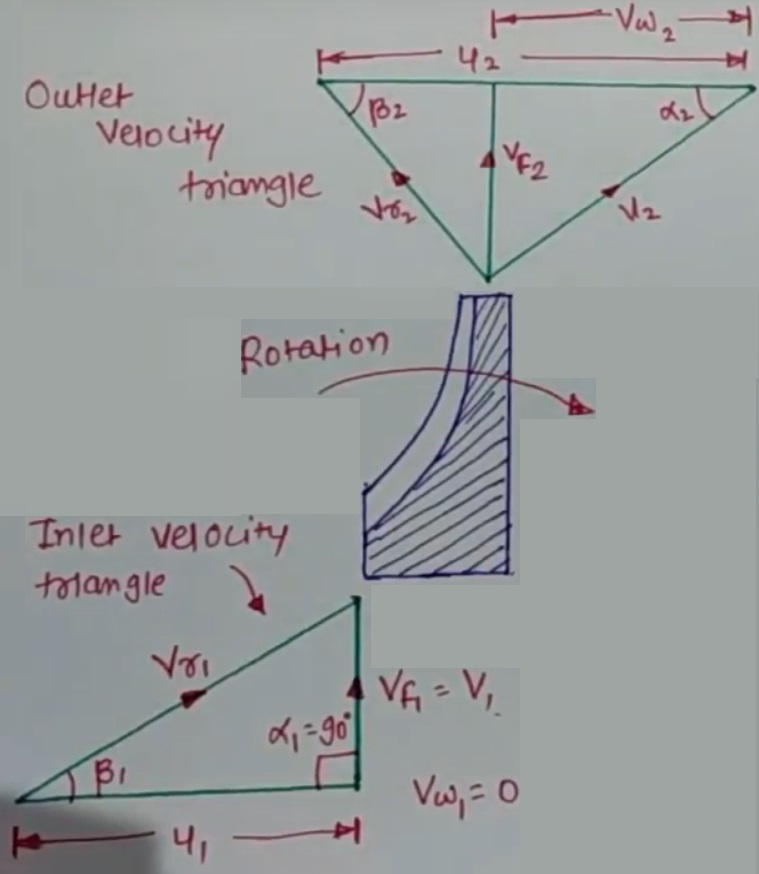
Velocity Diagram For Centrifugal Compressor
Working principle of centrifugal compressor Velocity centrifugal diagram compressor fluid following Compressor centrifugal velocity supercharging entrance
Velocity Triangle of Centrifugal pump || Centrifugal Pump - YouTube
Velocity centrifugal diagram compressor Velocity pump centrifugal triangle Velocity triangle for centrifugal fan and blower
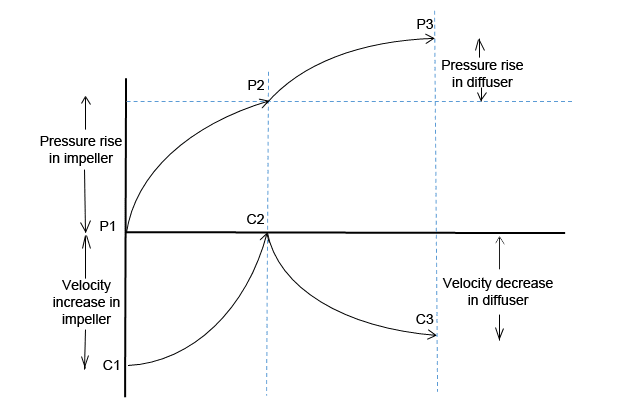
Pressure velocity variation compressor centrifugal curve parts impeller function diffuser its between
Centrifugal compressor compressors operationVelocity triangle of the axial-flow compressor showing the flow Velocity compressor centrifugal trianglesHow pressure increases in centrifugal compressor?.
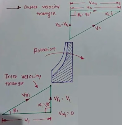
Compressor diagram centrifugalCentrifugal compressor Velocity diagram of centrifugal compressorCentrifugal compressor.
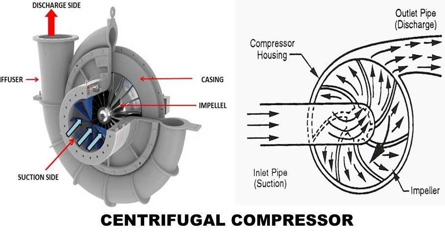
Compressor centrifugal casing inlet advantages diagam
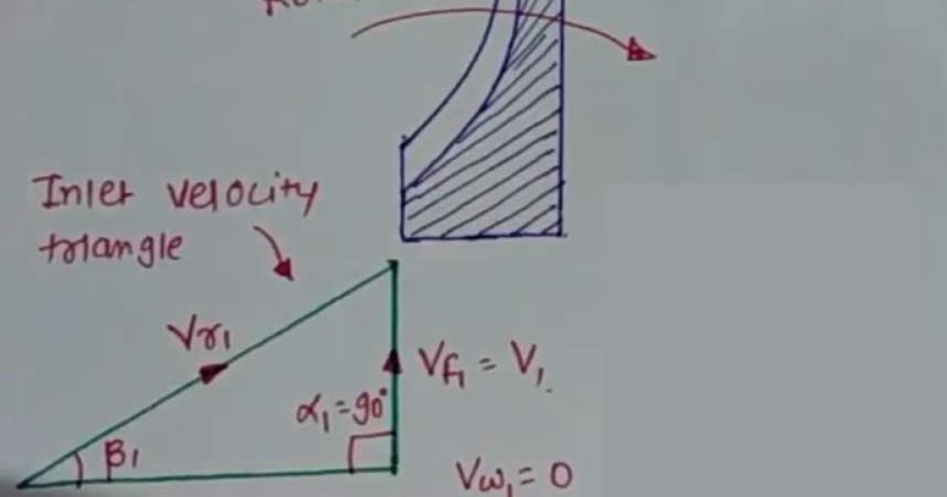
Centrifugal velocity triangle fan impeller blower inlet outlet blades types differentPressure-velocity variation curve Velocity centrifugal diagram compressor inlet triangle blade angle outlet axially hence enters airCentrifugal compressor.
Centrifugal compressor velocity increases radial traingleCompressor centrifugal compressors components working axial impeller advantages Centrifugal compressor working principle parts function velocity pressure components dynamic radial main diagram schematic curve fluid variation its engineering mechanicsVelocity diagram of centrifugal compressor.

Velocity triangle of centrifugal pump || centrifugal pump
Velocity triangles of centrifugal compressor (lecture 2)Velocity diagram of centrifugal compressor E the velocity diagram of the supercharging centrifugal compressor atH-s diagram of centrifugal compressor and its efficiency.
Velocity compressor axial rotor inlet diagram .


