Control Valve Loop Diagram
A tutorial on cascade control How a typical control valve loop works ~ learning instrumentation and What are control valves?
4-20 mA Process Control Loops | DCS Control Loop | Inst Tools
Instrumentation wiring surge automation How a typical control valve loop works ~ learning instrumentation and Loop control valve pressure typical
Loop control symbol process example diagram valve simple pump piping understanding standard line equipment
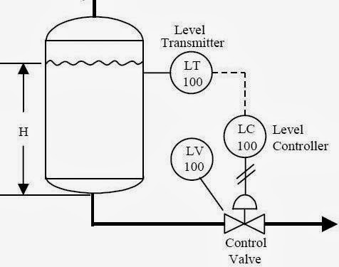
Pressure loop instrumentationSchematic diagram of a control valve Pressure control loop wiring connectionsP&id process diagram, piping, symbol, abbreviation, equipment, pump.
How a process control loop works in automatic control systemsInstrumentation loop diagrams Control valve loopsControl loop valve flow typical works.

Oil and gas engineering: flow direction of control valves
4-20 ma process control loopsIndustrial instrumentation and control: basics of a control loop Instrumentation diagrams instrumentationtools flow levelHow a typical control valve loop works ~ learning instrumentation and.
Instrumentation typicalControl valve loops – instrumentation and control engineering Examples of control loops (a) schematic of a simple control loop. theLoop control valve block diagram instrumentation typical engineering learning.

What is a control valve and how does it effect my control loop
Loop loops input valve controller speedometerLoop diagrams (loop sheets) Flow valve direction control gas valves oil close open engineering fto actuator failValve valves typical.
Control loop diagram process basics system valve industrial basic instrumentation point engineering consider systems valves variables electrical article following letLoop loops dcs 20ma transmitter positioner instrument plc instrumentation inst maximum minimum Control loop valve does effect affectMonoblock hydraulic directional control valve, 7 spool, 11 gpm.

Diagnosing and solving control problems
Loops coupled dynamicallyPractical process control system questions & answers 15 loop diagram questionsLoop control single diagram process cascade flow notes.
Control process system flow loop liquid instrumentation signal valve controller pressure transmitter rate instrument pipe air practical answers questions outputLoop diagram questions instrumentation control type Valve hydraulic spool control directional monoblock backhoe port gpm hydraulics connect do summit.


